Inverter Motor Control Diagram Dovol Dv300 4015 T 380v, 1.5k
3 phase inverter wiring diagram 12v to 230v inverter circuit diagram using 555 timer ic » inverters Inverter circuit diagram 1000w power spwm 12v watt dc board 1000 driven inverters process volt source ts idea big
Speed control of 3-ph Induction motor using VVVF Drive
Inverter circuits newcomers makingcircuits concerns economical possibly paragraphs Inverter control system diagram Inverter solar arduino driver pwm invertor trifazic schema circuits generator 380v mosfet panouri fasa tl494 12v integrat baterie solare electrica
Inverter 230v timer 240v inverters
Inverter circuit wave sine sg3525 using ic 3525 modified protection diagram low power output battery board projects watt simple controlTs big idea: 1000w power inverter circuit diagram Circuit inverter 100w simple diagramInverter control diagram..
Single phase 220 v 2.2 kw inverter of high performance vector inverterWiring diagram motor inverter plc micromaster siemens power connections electric enphase solar ac lc potentiometer filter Pin on powersMotor inverter wiring diagram.
Dovol dv300 4015 t 380v, 1.5kw frequency inverter motor control
Inverter 220v how2electronicsInverter circuit 500w, 12v to 220v Inverter control machinery phase kw performance vector high parts single motor[pdf] three phase inverter for induction motor control using fuzzy-pi.
Inverter motor control converters carving frequency machine 5kw 380v 220v 2kw 2022Phase control motor arduino induction inverter figure controller using three pi fuzzy 12 volt 1000 watt power inverter design process12v dc to 220v ac inverter circuit & pcb.

Inverter pulse voltage motor control speed inverters omron output form torque
Schematic of control part of inverter.Vfd wiring diagram with motor, switches, and external devices The voltage output from the inverter is in pulse form.Inverter 500w 220v 220vac 24vdc 300w 24v elettrico volt circuits eleccircuit transformer pcb schematics daya invertor rangkaian modifying watt mosfet.
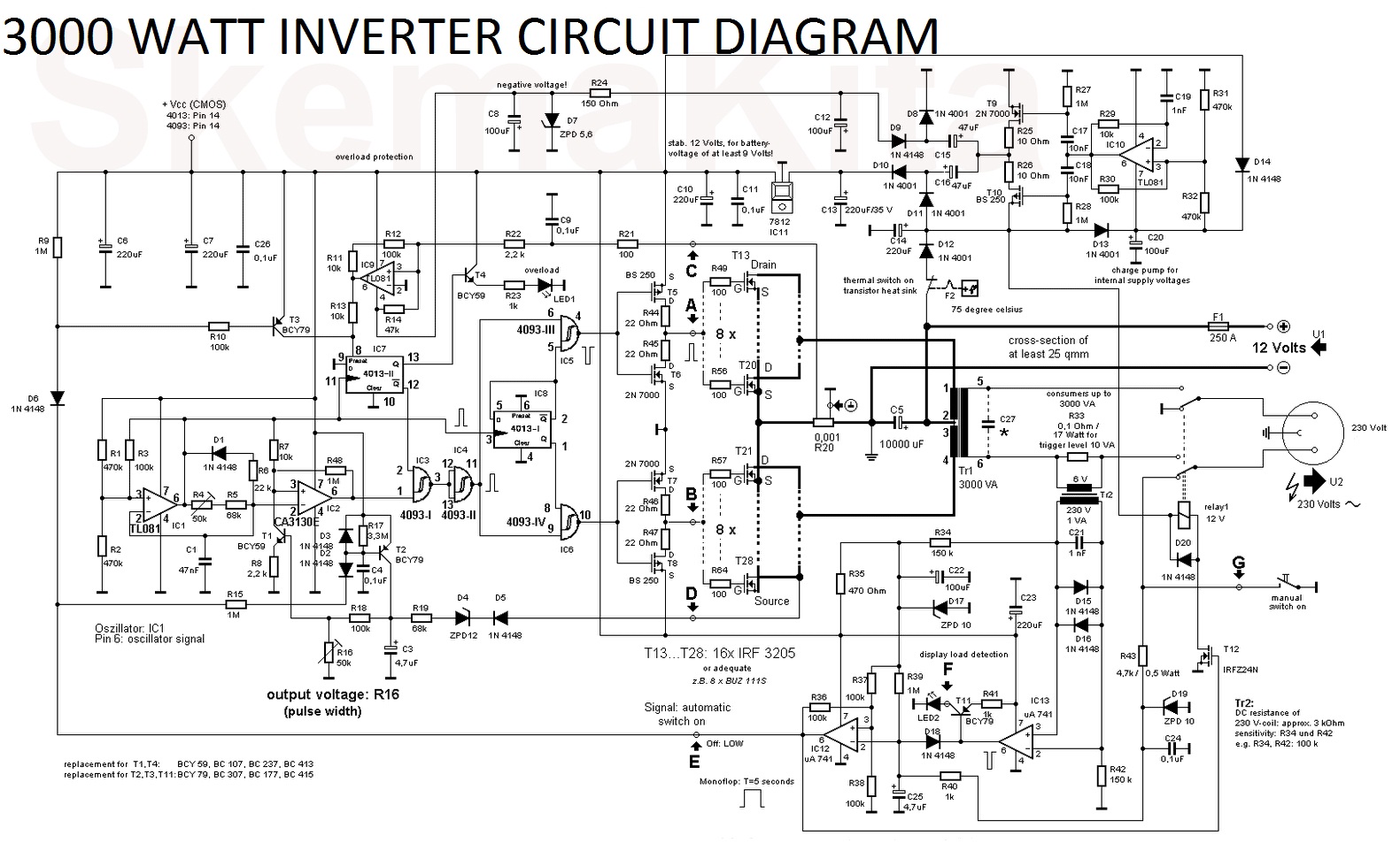
Inverter tl494 220v 3000w power dc 5000w schematics voltage watts supplyHow to reverse and forward a 3-phase motor using vfd? Inverter circuit diagram 1000w power spwm 12v watt dc 1000 board process inverters volt driven sourceSimple 100w inverter circuit.
Ac motor controller explained
Tl494 inverter circuit 3000w complete video tutorial (12[diagram] 3 phase inverter circuit diagram wiring schematic Circuit diagram of inverter air conditionerControl diagram of the inverter.
Inverter control system diagramInverter control diagram. Speed control of 3-ph induction motor using vvvf driveControl schematic of main inverter.

Sine wave inverter circuit diagram with full explanation
Inverter circuit diagram dc 12v to ac 220v 200w sine wave2.2kw 3hp 380v 5a 3 to 3 phase variable frequency inverter motor drive Heartwarming up and down motor control circuit viair wiring diagramInverter control.
Inverter circuit wave sine diagram board schematic power solar arduino full electronics projects inverters 1000w using diy 1kw charger icSchematic of the inverter control system. Pdf multilevel inverter block diagram pdf télécharger downloadInverter 12v diagram circuit 220v dc ac sine wave 200w schematic schematics diagrams gif.

7 simple inverter circuits for newcomers
.
.


![[DIAGRAM] 3 Phase Inverter Circuit Diagram Wiring Schematic - MYDIAGRAM](https://2.bp.blogspot.com/-z72AMcW5Xgo/UrLAgWypRzI/AAAAAAAAF84/j9mbCQybNMU/s1600/3+phase+inverter+driver+circuit.png)

